Toy Keyboard Reverse Engineering
I got a keyboard that goes to a toy computer. I don't have the computer but I have the keyboard. I wanted to see how it works so I took it apart. It uses a Macintosh-style 8-pin Mini-DIN connector. However, this is not RS-422 but rather provides a scanning interface.
I have taken photos of the top and bottom:
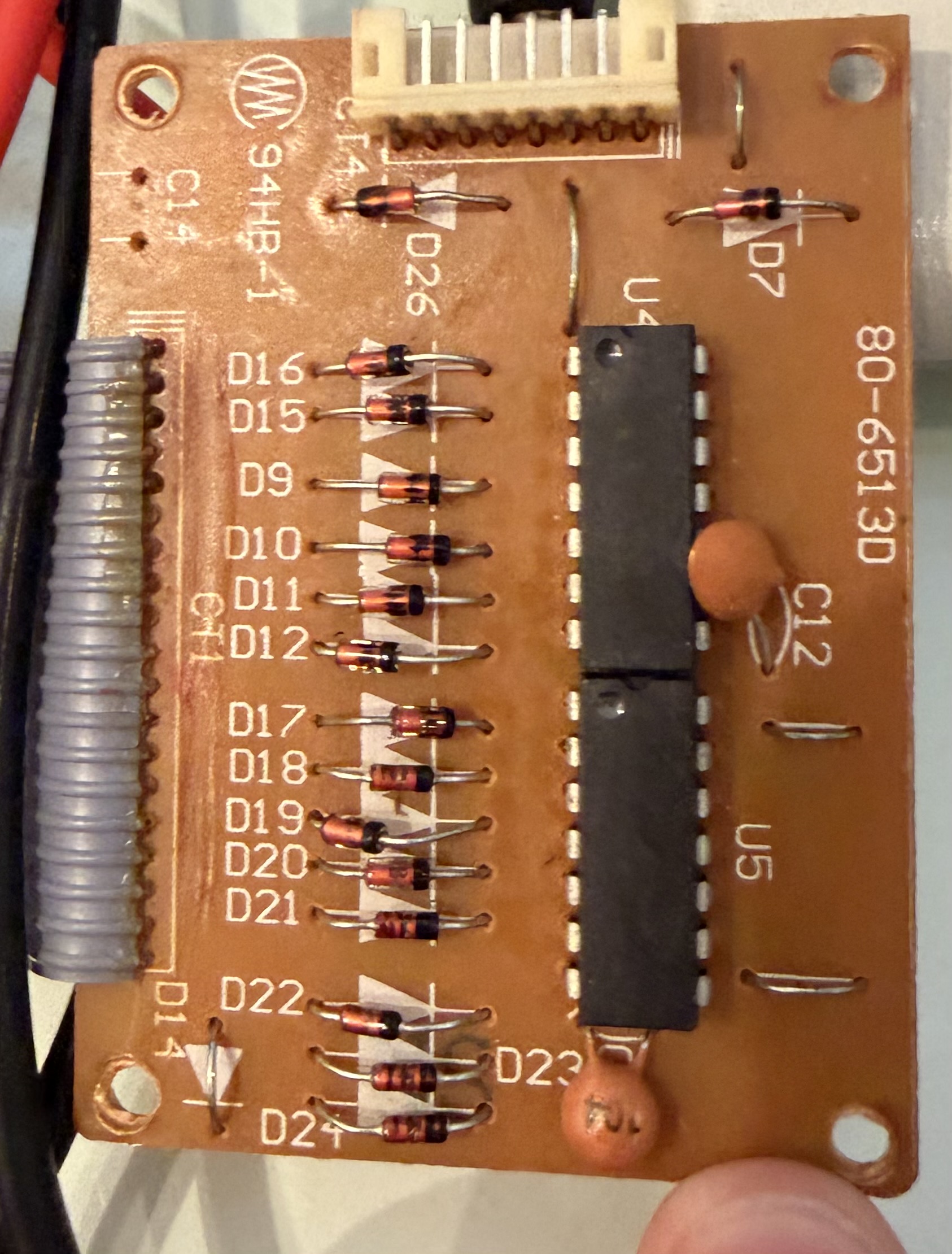
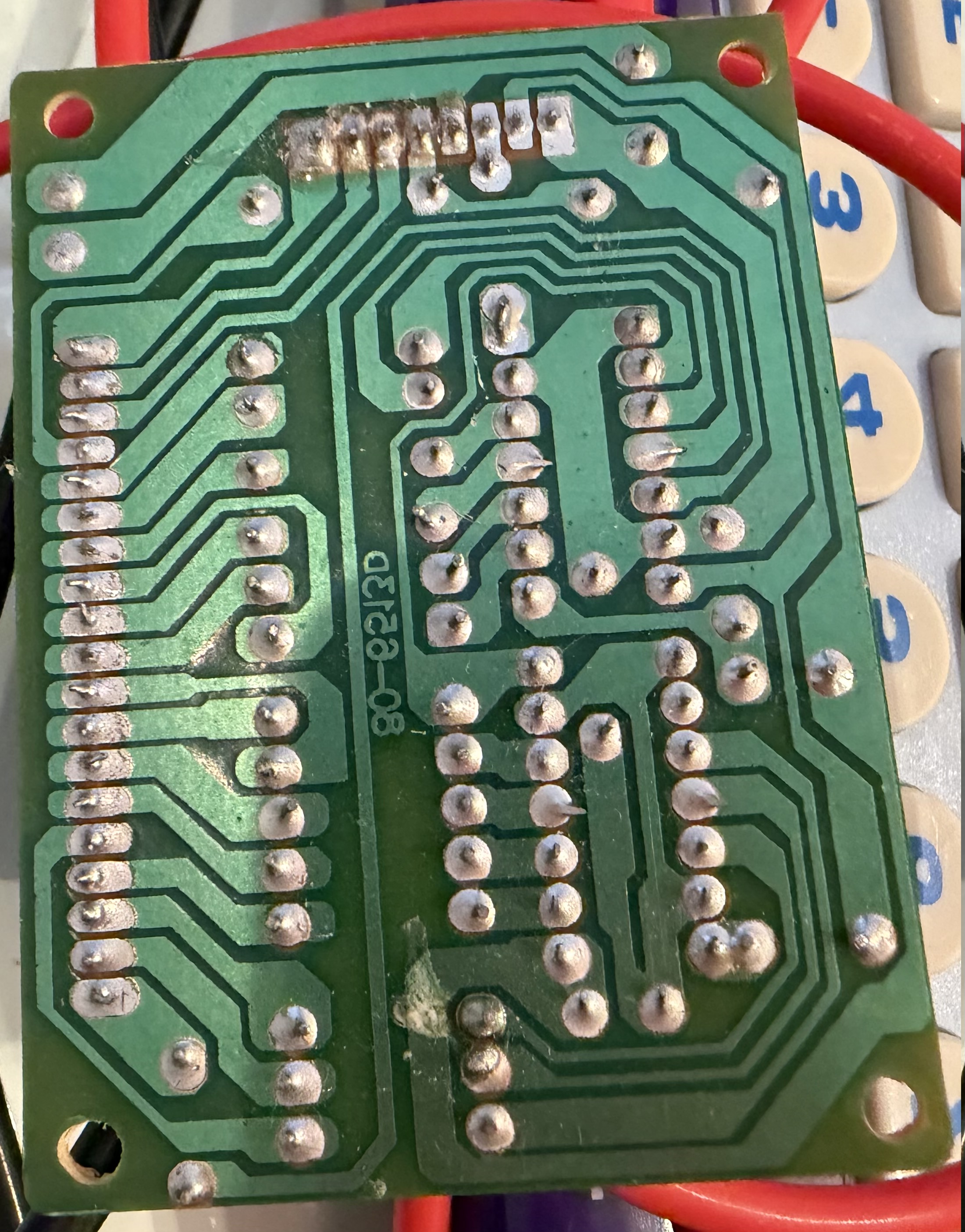
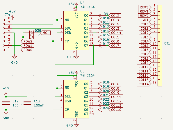
It is a shift-register (2x 74HC164) based design with 15 columns and 3 rows.
Scanning is performed by driving the "A" input low (normally high) and clocking through the columns.
The diodes will cause one of the row pins to be pulled down if the currently scanned column has a key pressed.
I assume inside the computer there are weak pull-ups to keep the row inputs high rather than let them float.
There are some interesting design decisions that have been made:
- There are decoupling capacitors on the two 74HC164 shift registers.
- COL14 has no diode but rather a jumper wire.
- Pin 4 of CT4 (to computer) drives two diodes. The purpose of this is unknown to me.
- D26: Connects to pin 4 of CT1 (to matrix)
- D7: Connects to the CLK pin of the shift registers.
To interface with this keyboard I am probably going to have to redo the matrix ribbon cable because it is fragile and likely has broken wires.
Schematic
I used KiCad to reverse engineer a schematic for this keyboard:
I made a timelapse of the process:
Last Updated 7/2/26